Light crossroads – Optical Quantum Gates in a Mach–Zehnder interferometer

Overview
Overview
Keywords: optics
Age group: 16+ years
Time frame: 90 minutes in the lab (plus preparation time for 3D printing etc.)
Required knowledge/skills: Students need basic knowledge of geometrical optics. It is helpful if they have gone through other lessons of this project, and have come across the bra-ket notation, a single qubit and its two basis states, quantum gates, and complex numbers.
Authors: Marco Nicolini & Chiara Colucci (IT)
Learning Outcomes
In this teaching unit, students learn to:
- explain interference as the result of phase differences between coherent paths;
- interpret the Mach–Zehnder interferometer as a physical realisation of a two-level ( qubit ) system;
- connect optical elements with quantum concepts such as superposition and measurement ;
- recognise the role of the Mach–Zehnder interferometer as a basic element of photonic quantum circuits.
Materials
In this teaching unit, we will build a Mach–Zehnder interferometer.

Figure 1: A Mach–Zehnder interferometer as 3D-printed
Required 3D-printed elements:
- a few 3 × 2 grids
- a laser box
- the following boxes:
- two lens boxes to accommodate two different lenses (f =15 mm and f = 26.5 mm)
- two 45° mirror boxes
- two beam splitter boxes
You will need to purchase:
- ball magnets (Ø 5mm)
- one or two screens
- a cylinder head screw, M3x12
- a nut, M3
- a hexagon head screw, M3x40
- some adhesive tape
- at least two mirrors (22 mm x 22 mm x 1.3 mm)
- at least two semi-transparent mirrors (40 mm x 30 mm)
- at least one lens OM2, Ø 16.5 mm, f = 15 mm
- at least one lens OA51-S, Ø 15 mm, f = 26.5 mm
We did not use the laser box in this teaching unit. Instead we used a red-light laser that was available in our lab. We did not need the screen either, but rather used the lab’s wall.
It is necessary to collimate the laser to see the interference fringes. Hint: make the adjustments without the lens in order to better see the spots that, at the end, need to overlap one another.
The various elements may be printed following the instructions under the following link: o3q.de[1]
The additional material that you will have to purchase can be found online: o3q.de/3d-dateien[2]
Theoretical background – The Mach–Zehnder interferometer
As already stated in teaching unit Playing with Light, light consists of photons. Experiments with individual photons are difficult to carry out in school, so we have to be content with the fact that our observations reflect the behaviour of a light beam consisting of many photons. However, the photons in a laser beam generally do not interact with each other. This means that we can assume that the laser beams in our optical experiments consist entirely of individual photons. And that the observations we make are consistent with experiments with individual photons.
In a Mach–Zehnder interferometer, a light beam first hits a beam splitter and is split into two light beams. The two light beams then hit a second beam splitter, which results in the beams recombining to one beam. Depending on the phase difference between the two beams, an interference pattern can be observed on the screens behind the second beam splitter.
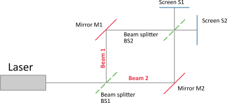
Figure 2: Setup of a Mach–Zehnder interferometer with two reflective mirrors (M1 and M2) and two semi-transparent mirrors which act as beam splitters (BS1 and BS2).
We make the following assumptions:
- In the interferometer, we operate with ideal beam splitters and ideal mirrors.
- Mirrors introduce a phase shift of 180° upon reflection.
- Beam splitters introduce a phase shift of 90° upon reflection (some real beam splitters introduce a phase shift of 180° at the front surface, and no phase shift at the rear surface).
- No phase shift occurs upon transmission.
- The light energy (and thus the light intensity) is preserved at the mirrors and beam splitters.
- If we (theoretically) send one photon into the Mach–Zehnder interferometer, only one photon comes out.
The phase shifts in a Mach–Zehnder interferometer are shown in fig. 3 (for beam 1) and fig. 4 (for beam 2). The beam splitter BS1 splits the laser beam into a beam going straight (beam 2) and a beam that is reflected upwards (beam 1). The two beams are phase-shifted by 90° relative to each other, as beam 1 is reflected by BS1.
Beam 1 then hits mirror M1, where it is reflected again and thus phase-shifted by another 180°. It then hits the beam splitter BS2, where it either passes straight through or is reflected and shifted by another 90°. In the direction of screen S1, the total phase shift amounts to 90° + 180° + 90° = 360°, while in the direction of screen S2, the phase shift amounts to 90° + 180° = 270°.
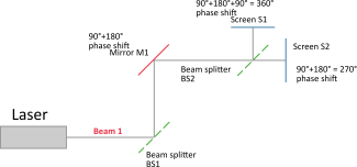
Figure 3: The path of beam 1 with all the phase shifts in a Mach–Zehnder interferometer
Beam 2 passes straight through the beam splitter BS2 and is then reflected by mirror M2 and phase-shifted by 180°. It then hits the beam splitter BS2, where there are again two options: the beam passes through beam splitter BS2 and hits screen S1 with a phase shift of 180°, or it is reflected at BS2 and hits screen S2 with a phase shift of 180° + 90° = 270°.
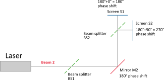
Figure 4: The path of beam 2 with all the phase shifts in a Mach–Zehnder interferometer
At the end, the interference pattern that we observe on the two screens (S1 and S2) is caused by the two beams 1 and 2 being superimposed and having different phase shifts. Hence:
- On the screen S1, we observe a destructive interference between beam 1 and beam 2. Beam 1 has a 360° phase shift and beam 2 a 180° phase shift, meaning that the two beams are out of phase by 180°.
- On the screen S2, we observe a constructive interference between beam 1 and beam 2. Both beam 1 and beam 2 have a 270° phase shift, meaning that they are in phase.
Finally, we must consider that the cross section of the laser beam has a certain diameter (not constant along the beam and not point-like), which creates additional interference patterns on the two screens.
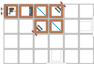
Figure 5: A Mach–Zehnder interferometer as built using the instructions
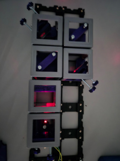
Figure 6: The set-up of the self-built Mach–Zehnder interferometer
Tasks for students and teachers
The teacher hands out set-up scheme of a Mach–Zehnder interferometer (see fig. 5) and stress some assumptions:
- All optical elements are ideal.
- The light source is monochromatic and coherent.
- The beam splitters are thin (no phase shift when light goes straight through them).
- The two light paths between the two beam splitters (the “arms”) have the same length.
The Mach–Zehnder interferometer is a device which allows the students to create a phase shift and observe an interference pattern. Since there is a single incoming laser beam, this experiment allows to simulate a single photon which interferes with itself.
A photon can take two paths in the Mach–Zehnder interferometer: the path of beam 1 or the path of beam 2. If we remove the second beam splitter (BS2), we know that a photon that takes the lower path (beam 2) will arrive at screen S1, while a photon that takes the upper path (beam 1) will arrive at screen S2.
Students can manipulate the interferometer setup to predict and observe what happens at the screens in all the above cases.
Using the worksheet, students visualize and model the Mach–Zehnder interferometer by sketching the optical paths and inserting the corresponding phase shifts. The worksheet can be downloaded as pdf and docx.
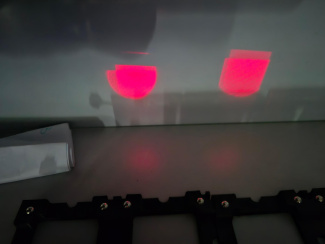
Figure 7a: The two emerging patterns from the two screens and a detail with fringes
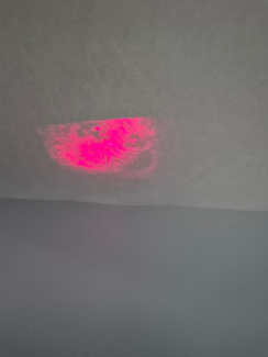
Figure 7b: One of the beams has been deflected onto the wall with a mirror, in order to see the two beam patterns next to each other.
The connection to quantum computing
Now let's take a giant leap towards the topic of quantum computing. At this point, students should already have heard something about qubits (and their basis states), quantum gates and should be familiar with the bra-ket notation. You find introductions to these concepts in Basic Concepts of Quantum Computing.
The basic building blocks of a quantum computer are qubits and quantum gates. A qubit can be physically created in various ways. The important thing is that it is ‘something’ that can be in two (independent) states. In the previous teaching unit (Playing with Light) we saw that polarisation directions could be used as the two basis vectors. These two basis vectors can be taken as basis states of a qubit. We see in the next teaching unit (Splitting and Reuniting Laser Beams - With Birefringent Crystals) that photons can be send on two different paths according to these two polarisation states (by means of birefringent crystals for instance). Here we will use the different paths (“which-way-information”) of light as the two basis states. corresponds to one way and to the other way through the interferometer.
and
We can consider the beam splitters or the mirrors in a Mach–Zehnder interferometer or even the entire interferometer as quantum gates, with which we can generate superposition, among other things.
Firstly, there are two ideal Beam Splitters BS1 and BS2 which corresponds to a matrix as each beam splitter has two inputs and two outputs. The two inputs will be called , and , being the two perpendicular directions where photons can actually reach the splitter (see figure below).
Let's first take a look at a beam splitter. Its ‘input’ can, for example, be a photon coming from the horizontal input path or a photon coming from the vertical input path. The beam splitter has two outputs and . The result is a photon being in a superposition of and .
The analogy is again: which way information = qubit and beam splitter = quantum gate.
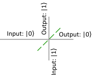
Figure 8: The beam splitter as “quantum gate” with 4 logical ports: 2 inputs and 2 outputs
A ‘beam splitter’ quantum gate can be described by the following matrix:
A photon in the state hitting this ‘beam splitter’ quantum gate can be represented mathematically as follows:
Or, written as a function of the basis states of the qubit:
The ‘photon qubit’ leaving the beam splitter is in a so-called superposition of the basis states and . If a measurement were to be performed behind the beam splitter, the probability of finding the ‘photon qubit’ in the state would be:
And the probability of finding it in the state would also be .
The two mirrors can also be regarded as quantum gates. A mirror causes a phase shift of 180°. A ‘mirror’ quantum gate can be represented by the following matrix:
,
where is the identity matrix.
Since both beam 1 and beam 2 are reflected at a mirror, the phase shift is irrelevant (both are equal; this is referred to as a global phase, which has no physical effect). This means that in fig. 3 and fig. 4, we can cancel out ‘180°’ everywhere on screens S1 and S2. See also fig. 9.
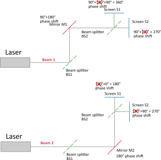
Figure 9: There is a phase shift of 180° on each path of the photon (four possible paths). We therefore do not need to take this so-called ‘global phase’ into account.
Now let's add the second ‘beam splitter quantum gate’. The effect of beam splitter BS1, mirror M1 (or M2) and beam splitter BS2 can be described in matrix form as:
This is the matrix notation of the quantum gate that represents the whole Mach–Zehnder interferometer (MZI):
We could now apply this ‚MZI‘ quantum gate to a general qubit state:
How can this be interpreted? The Mach–Zehnder interferometer acts on a photon by exchanging the two amplitudes of the basis states.
As we have seen, the optical elements in a Mach–Zehnder interferometer can be used as quantum gates.
In some optical quantum computers several Mach–Zehnder interferometers and additional optical elements are coupled together in order to apply several quantum gates and do complete calculations.
O3Q.de – Low-Cost Experimente zur Wellen- und Quantenoptik
(last accessed 20.03.2026)O3Q.de – 3D-Dateien
(last accessed 20.03.2026)Ghirardi, Gian Carlo. "Un’occhiata alle carte di Dio: Gli interrogativi che la scienza moderna pone all’uomo" Il Saggiatore, Milano, 1997.
Bondani, Maria. "Single‑photon Mach‑Zehnder interferometry for High Schools." Journal of Physics: Conference Series, vol. 1929, no. 1, 2021.
M.Michelini, G.Zuccarini. "Promoting the transition to quantum thinking: development of a secondary school course for addressing knowledge revision, organization, and epistemological challenges" Cornell University ARXIV, 2022.
Share this page