Quantum Superposition and Entanglement Simulation

Overview
Overview
Keywords: Quantum simulation, superposition, entanglement, Arduino, visualisation, Tinkercad circuits
Age group: 14-17
Required knowledge/skills: Basic electronics, Arduino programming, circuit design, working in tinkercad.com virtual environment, basic understanding of quantum concepts
Time frame: 1-2 hours per simulator: assembling the circuit in Tinkercad and uploading simple Arduino code to the microcontroller(s) to simulate superposition and/or entanglement (like LED blinking patterns).
Authors: Astrinos Tsoutsoudakis (GR)

Required materials
- Software: Arduino IDE
- Online tool: www.tinkercad.com
Hardware (if building the actual circuit)
For the superposition simulator
| Name | Quantity | Component |
|---|---|---|
| U1 | 1 | Arduino Uno R3 |
| D1 | 1 | RCBG LED RGB |
| Rpot1 | 1 | 250 kΩ Potentiometer |
| S1 | 1 | Slide switch |
| R1 / R2 | 2 | 220 Ω Resistor |
| R3 / R4 | 2 | 10 kΩ Resistor |
| S2 | 1 | Pushbutton |
For the entanglement simulator
| Name | Quantity | Component |
|---|---|---|
| UA / UB | 2 | Arduino Uno R3 |
| D1 / D2 | 2 | RCBG LED RGB |
| S1 / S2 | 2 | Pushbutton |
| S3 / S4 | 2 | Slide switch |
| R1 / R2 / R3 / R4 | 4 | 10 kΩ Resistor |
| R5 / R6 / R7 / R8 | 4 | 220 Ω Resistor |
Tasks for teachers
- Set up Tinkercad classrooms, provide Arduino code templates, circuit diagrams.
- Introduce quantum concepts and explain superposition and entanglement simply (see other lessons in this project).
- Show how the circuit simulates superposition and entanglement through LEDs blinking, fading, or reacting to switches.
- Help students place components correctly: LEDs, resistors, buttons, slide switches.
- Provide support for coding activities.
- Encourage inquiry and discussion.
- Use short quizzes, discussion, or mini-presentations to check comprehension.
Tasks for students
- Learn basic electronics and coding.
- Assemble the circuit in Tinkercad, upload and modify code.
- Experiment with the superposition and entanglement simulator.
- Document what they did and present findings and difficulties.
- Think creatively about how to make the simulation even closer to real quantum systems and suggest improvements.
The superposition simulator
You find the Tinkercad simulation for reuse here.
In the strange world of quantum physics, particles like electrons or photons don’t simply exist in one state or another – they can exist in multiple states at once, a phenomenon called superposition . The Arduino circuit that will be built in this lesson mimics a quantum system being in a superposition of two basis states, and . Until a measurement is performed, one can only give probabilities as to whether the system is in state or in state .
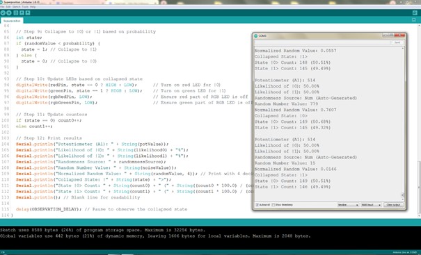
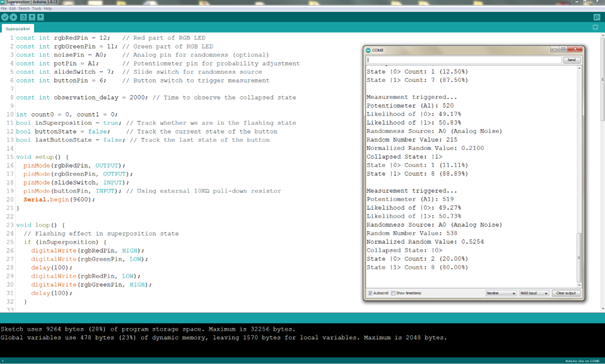
In the electronic circuit that we will design with Tinkercad and build with Arduino and electronic elements (like control LEDs, buttons, and switches), these probabilities will be simulated using the randomness generated from Arduino's analogRead() function and the fluctuating noise from an unused analogue pin.
To introduce adjustable “probabilities” that will collapse into a concrete measured value, we can use a potentiometer. By reading the potentiometer's value with analogRead(), we can adjust the likelihood of collapse (reduction) of the state into state or .
The RGB LED glows during the “superposition” phase and after the “measurement,” the LED turns either red () or green (). The loop continuously resets the system, demonstrating the important concepts of superposition and measurement in quantum physics.
The pushbutton in the pictured circuit design is responsible for taking the measurement, while the slide switch alternates between the two randomness generators.
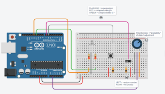
A circuit simulating superposition realised in the tinkercad.com virtual environment
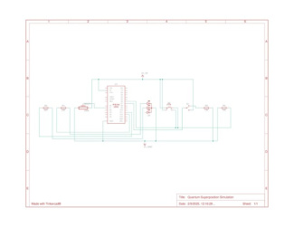
Circuit diagram for simulating superposition
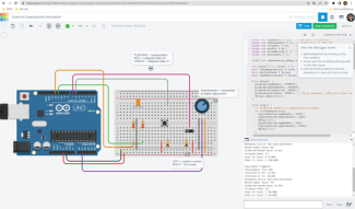
The circuit simulated in tinkercad.com environment
Note that when randomness is set to come from the unconnected pin A0, that source is biased (the predicted likelihood is different from the actual results, see next picture) toward the potentiometer value, because all analogue pins share the same ADC (Analog-to-Digital Converter) bus. This means they are multiplexed into a single ADC, and only one pin can be read at a time as the ADC sequentially switches between them.
To reduce this bias and make things more interesting, we can connect a bare wire of 10–20 cm to an analogue input pin (such as A0 on an Arduino) and leave it floating (unconnected to voltage or ground). This allows it to pick up environmental noise — especially electromagnetic noise from nearby electronics, lights, Wi-Fi, or even from our own body when we approach or touch the wire.
The entanglement simulator
You find the Tinkercad simulation for reuse here.
Quantum concepts like entanglement are hard to grasp as they don’t have a direct analogy in our experience of daily life. A simulation enables students to visualise this concept. In this activity, students can create two entangled objects that are linked to each other so that if one object is measured (for example, it changes its initial colour from blue to red), the other object instantly changes its state too in a predefined way (for example, it changes its initial colour from green to yellow), demonstrating how the two objects are “linked together”. In quantum physics we call this entanglement.
The simulation helps students understand the difference between quantum entanglement and a classical correlation. In a classical world, imagine placing two balls (each with a known colour, let’s say red and blue) into two separate boxes. If you open one box and find a red ball, you immediately know that the other box contains a blue ball. This is a correlation, but not entanglement, because the states (that is, the colours) were determined from the start. The quantum entanglement simulation demonstrates that the states remain undetermined until a measurement is made.
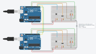
A circuit simulating entanglement realised in the tinkercad.com virtual environment
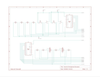
Circuit diagram for simulating entanglement
https://scienceexchange.caltech.edu/topics/quantum-science-explained/entanglement
https://docs.arduino.cc/language-reference/en/functions/communication/serial/
https://www.analog.com/en/resources/analog-dialogue/articles
https://scienceexchange.caltech.edu/topics/quantum-science-explained
https://docs.arduino.cc/learn/microcontrollers/analog-input/
https://www.analog.com/en/resources/analog-dialogue/articles/adc-input-noise.html
https://knowledge.ni.com/KnowledgeArticleDetails?id=kA00Z000000P9mKSAS
Share this page