Splitting and Reuniting Laser Beams - With Birefringent Crystals

Overview
Overview
Keywords: light polarisation, crystal, birefringence, polarisation filter
Age group: 16+
Required knowledge/skills: elementary goniometry, polarisation, vectors
Time frame: 90 minutes
Authors: Marco Nicolini & Chiara Colucci (IT)

Material
- a laboratory laser
- safety goggles
- two calcite crystals
- a polarisation filter
You can download the additional worksheet "The big question" here as PDF- or docx.
Learning outcomes
This teaching unit allows the students:
- to become familiar with light polarisation;
- to comprehend, at the end of the unit, what a superposition state of a photon looks like.
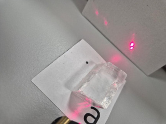
Fig. 1: A calcite crystal and a laser beam
Conceptual introduction
In the units “Playing with Light” and “Light crossroads” we introduced experimental setups that could be used to simulate quantum superposition of a qubit. In this lesson, we will introduce another method that requires even simpler materials: a small laboratory laser, two calcite crystals and a polarisation filter.
Theoretical background
Calcite is a transparent mineral made of calcium carbonate (CaCO₃) with a special optical property, which is called birefringence, or double refraction.
When a laser beam passes through a calcite crystal, the crystal splits the incoming beam into two separate beams (rays) that travel at different speeds and are polarised in different directions. When looking through a calcite crystal, you ‘see everything double’.
The optical axis of a crystal is a direction in which a beam of light is not affected by birefringence If a beam of light is parallel to the optical axis, it shows no birefringence.
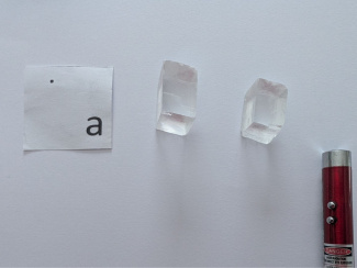
Fig. 2: Material for the experiment: two calcite crystals, a laser, a letter printed on a sheet of paper
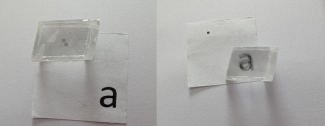
Fig. 3: When putting the birefringent crystal on the letter, one sees it twice.
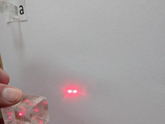
Fig. 4: After the laser beam has gone through the crystal, two laser beams appear on the screen (the wall).
The two rays are called: ordinary ray (o-ray) and the extraordinary ray (e-ray). Their characteristics are:
The o-ray:
- Travels through the crystal at a constant speed.
- Follows Snell’s law for isotropic media (normal refraction rules).
- Its polarisation direction is perpendicular to the crystal’s optical axis.
The e-ray:
- Travels through the crystal at different speeds depending on the orientation of the crystal.
- Does not follow Snell’s law.
- Its polarisation direction is parallel to the crystal’s optical axis.
Our main focus will be, once more, the polarising property of the calcite crystal. We can use a polarisation filter (see unit “Playing with Light”) to show that the polarisation directions of the two rays are perpendicular.
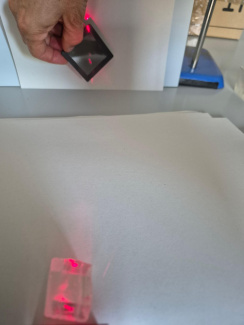
Fig. 5: The laser beam exiting the crystal hits a polarisation filter
To link this experiment to our topic of quantum computing, we assign the horizontally polarised beam to the ket vector and the vertically polarised beam to the ket vector . More on this below.
The birefringent property of the calcite crystal has the following effect: when using a second crystal, the two beams reunite to one single beam. To achieve this, you “just” need to find the proper (matching) crystal surfaces and orientations, which give you one single image or one single beam instead of two.
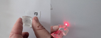
Fig. 6: If you place the ‘correct’ surfaces of the crystal on top of each other, you will see a single image and a single beam.
Experiment
In the following experiment, we use light that has both a horizontal and a vertical polarisation component. This can be achieved with light having a 45° polarisation direction. Since we use a cheap laser, its light is already polarised. We only need to determine the specific polarisation direction, which is easily done using a polarisation filter (see the unit “Playing with Light” Remark about lab lasers). Once we know the polarisation direction of the laser beam, we direct it onto the calcite crystal so that the polarisation direction of the laser and the optical axis of the crystal form an angle of 45° – at the same time, the laser beam is directed onto the crystal so that the direction of propagation of the light and the optical axis of the crystal are perpendicular to each other.
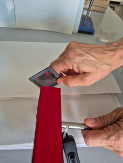
Fig. 7: Determining the polarisation direction of the laser beam with a polarisation filter
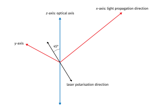
Fig. 8a: The directions of the optical axis, laser light polarisation and beam propagation
Now we take the second calcite crystal and place it directly behind the first one. We rotate the second crystal until the two beams become one beam again. We expect that the beam (of photons) exiting from the second crystal has the same properties as the two beams exiting from the first crystal, which means that this beam is polarised both horizontally and vertically in equal proportions. In the particle image, this can be described as follows: the emerging photons are equally likely to be horizontally polarised photons or vertically polarised photons.
To verify this assumption, we use the polarisation filter and orient it so that its polarisation direction is 45° with respect to the polarisation direction of the laser beam. Half of the horizontally polarised photons and half of the vertically polarised photons should pass through the polarisation filter, i.e. half of the photon that passed through the first calcite crystal: The light intensity after the second polarisation filter therefore should correspond to half of the light intensity of the incident laser beam.
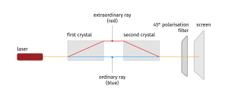
Fig. 8b: Experimental set-up
Actually, the results we observe are different from what is expected (in a classical particle model): the intensity (i.e. energy of a photon times number of photons divided by cross sectional area) of the laser beam exiting the two crystals does not show any attenuation, meaning that all the photons must have passed through them – independently of their polarisation.
What is the path followed by the photons reaching the screen? Classical physics allows for three possible answers:
- The photons take either one path or the other. However, this contradicts what we see on the screen, namely that the intensity of the laser beam remains unchanged. We know that the rays in the calcite crystal are either polarised vertically or horizontally, meaning that for both rays, only 50% of the light (and thus light intensity!) passes through the 45° polarisation filter.
- Each photon takes both paths simultaneously. This is not possible because single photons cannot be divided.
- The photons do not take either of the two paths but rather follows a different trajectory. This can easily be refuted by placing a light-blocking screen in one or both paths. If only one beam is blocked, only 50% of the photons reach the rear screen (or wall). If both beams are blocked, no photons reach the rear screen. Therefore, only the two paths described in the experiment are possible.
The answer is simple, but astonishing: photons can exist in a so-called superposition state. In a sense, they travel both paths at the same time.
Let's jump back to our topic of quantum computing and describe the state of the photon as: This reads as: The photon (described by its state ) is in a superposition state consisting of a horizontally polarised photon and a vertically polarised photon ). The probability that the photon is horizontally polarised is and the probability that it is vertically polarised is . In our specific case, . This means that the photon has a probability of (i.e. 50%) of being horizontally polarised and an equal probability of 50% of being vertically polarised.
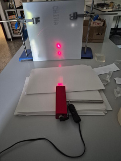
Fig. 9: The laser and a calcite crystal splitting the ray into two rays – one being polarised horizontally and the other one polarised vertically.
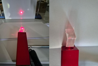
Fig. 10: The recombined beam after passing through the two crystals (left) and the two crystals seen from above (right)
So, we have left the macro world, where the laws of classical physics apply. For quantum objects such as photons, we have to apply the laws of quantum physics.
The statement ‘The photon is in a superposition state’ differs fundamentally from (classical) statements such as “The photon reached the screen via one of the two paths”, or “The photon took both paths simultaneously”, or “The photon took a different, undetectable path”.
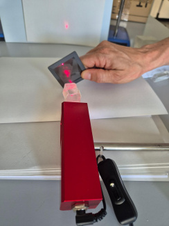
Fig. 11: The final result of the experiment: the intensity of the laser beam behind the two calcite crystals corresponds to the intensity of the beam exiting the laser.
What would happen, for example, if one were to check whether the photon had taken the path of the extraordinary beam? As soon as one checks, which means nothing more than performing a measurement, the result is clear: one then knows whether the photon took this path or not. This is referred to as the . But as long as we do not check, the photon remains in a state of superposition.
From a philosophical point of view, we must admit that our language does not help us to understand quantum physics: the words that we use in our everyday language or to describe classical physical phenomena in the macroscopic world, words that have developed over thousands of years on the basis of human experience and our senses, are useless when we need to express in words what we cannot directly observe: the “quantum world”. We need to be open-minded and accept that this time, only physics with its specific language and mathematics with its symbols were able to help us out.
Watch the Birefringent crystals animation on YouTube below:
O3Q.de – Low-Cost Experimente zur Wellen- und Quantenoptik
(last accessed 20.03.2026)Ghirardi, Gian Carlo. "Un’occhiata alle carte di Dio: Gli interrogativi che la scienza moderna pone all’uomo" Il Saggiatore, Milano, 1997.
Bondani, Maria. "Single‑photon Mach‑Zehnder interferometry for High Schools." Journal of Physics: Conference Series, vol. 1929, no. 1, 2021.
M.Michelini, G.Zuccarini. "Promoting the transition to quantum thinking: development of a secondary school course for addressing knowledge revision, organization, and epistemological challenges" Cornell University ARXIV, 2022.
Share this page