Playing with Light

Overview
Overview
Keywords: optics, trigonometry, vectors
Age group: 16+
Required knowledge/skills: Reviewing classical properties of light as a wave might be useful. For a mathematical interpretation of what is observed, the students need a basic knowledge of trigonometry, and they need to know how to break down a vector into its components in a Cartesian coordinate system.
Time frame: 90 minutes in the lab – investigating the polarisation of laser light, inserting three polarisation filters, discussion
Authors: Marco Nicolini & Chiara Colucci (IT)

Learning outcomes
In this teaching unit, students learn to:
- describe polarisation as a physical property of light and explain how polarisation filters work;
- apply Malus’ law in terms of light intensity;
- replace the concept of intensity in Malus’ law with a concept of probabilities for a small number of photons or even single photons;
- understand polarisation states as mutually exclusive basis states of a two-level system;
- recognise superposition as a key concept emerging from polarisation experiments.
If teachers want their students to study the behaviour of light through experiments, they can show them that light can be explained and modelled both as a wave and as particles, the so-called photons. When its intensity is high, light behaves like a wave – for example in polarisation experiments and in interferometers. When its intensity is low, however, experiments show that light behaves like particles.
There is a field in physics where this distinction does not apply, and we need to accept that light with small intensity shows both wave and particle behaviour: welcome into the world of quantum mechanics, where entities need to be considered sometimes as waves and sometimes as particles! We call these entities “quantum objects”. We will focus on the physics required to understand how quantum computers work. Students will have to find logical interpretations of what they observe whereas teachers help students to find this logical path through the evidence.
The unit is thought of as a collection of experiments which can be carried out consecutively or individually.
Experiment 1 (Warming up)
Material
- Old LCD screen
- Polarised glasses
- Polarisation filters
- Calcite crystal
- Simple colour filters (frequency filters) – to compare/differentiate their effect with the one of polarisation filters). Non-polarised sunglasses will work perfectly
An experiment to break the ice could be the following: a computer is connected to an “old” LCD screen (that is not used anymore). The screen has to be set up for the purpose by peeling off the top layer. Beforehand, the teacher typed some words that appear on the screen.
Some of the students are given polarised glasses or polarisation filters, while others are given simple colour filters.
Outcome
Only the students who look through the polarisation filters or polarised glasses will be able to read the words on the screen. Those with the colour filters (or sunglasses) will see only a uniform background: without a polariser, the image on the LCD screen is not visible.
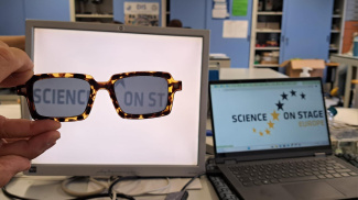
Fig. 1: left: LCD screen without the top layer; right: normal screen. The image on the two screens is the same, but on the left, it is not visible unless you wear a pair of polarised glasses!
An LCD is made up of several functional layers:
- Backlight (LED or fluorescent lamp)
- Polarisation filter
- Liquid crystal layer
- Colour filters (RGB)
- Second polarisation filter (facing the viewer)
Without the top layer polarisation filter, the light that is modulated by the liquid crystals cannot be turned into colour differences. Our eyes receive light that no longer has the contrast effect from the first polarisation filter and the liquid crystal layer. The screen looks mostly white.
An LCD works like this:
- The backlight emits unpolarised light.
- The rear polarisation filter polarises light in one direction.
- The liquid crystals rotate (or not) the polarisation depending on the electrical signal.
- The front polarisation filter (the analyser) selects the correct component only: if rotated properly, light passes (pixel on); if not, it is blocked (pixel off).
If you remove the front polariser, the rotated light is no longer analysed. That means there is no visible difference between “on” and “off” pixels.
Polarisation
Light is an electromagnetic wave travelling in space and carrying energy. The electric and the magnetic field make up the electromagnetic wave. These fields oscillate in phase, orthogonally to one another.
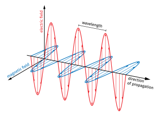
Fig. 2: A propagating electromagnetic wave
The electromagnetic wave can oscillate in any plane containing the black line in fig. 2, which depicts the propagation direction of the wave. The light we receive from the sun or the light we switch on at night are examples of unpolarised light.
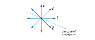
Fig. 3: Unpolarised light with its electric field in all directions perpendicular to the direction of propagation.
One can polarise unpolarised light: the electric field then oscillates in only one plane, whereas the magnetic field oscillates in a plane that is orthogonal to that plane.
The polarisation of light can be described with the help of a cardboard model.
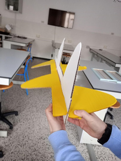
Fig. 4: Model of the electric and magnetic field of a light wave
The model can be used for two different applications:
- Application 1: The electric and the magnetic fields which oscillate perpendicularly to each other (fig. 4)
- Application 2: The model shows the two components of the electric (or the two components of the magnetic field) before passing through a polarisation filter. (fig. 6)
The yellow and the white parts show the oscillations of the two perpendicular components of one of the two fields e.g. the electric field. Both are perpendicular to the direction of propagation (one component is yellow and the other one is white). The cardboard profile can be rotated along its axis to demonstrate how unpolarised light behaves. The teacher needs to clarify that the magnetic field is not visible in this model.
Polarised light can sometimes be observed naturally when light is reflected at a surface. In the lab, we can create polarised light using thin films called polarisation filters (or polarisers). A polarisation filter allows light in a specific polarisation place to pass through and absorbs all other light. In other words, only the waves with an oscillating nonzero component parallel to the direction allowed by the polarisation filter can get through. As a result, the intensity of light passing through the filter is reduced.
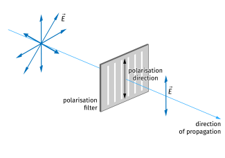
Fig. 5: Generating polarised light with a polarisation filter
Polarisation filters that employed herapathite crystals were invented by Edwin Land in 1936. These crystals are characterised by long chains with free electrons that can vibrate. When light strikes these thin sheets, the electric field vibrating in the direction of the chains transfers its energy to the crystals and is thereby being absorbed. Only light whose electric field oscillates perpendicularly to the chains can pass through the crystals. The so-called transmission axis of the polarisation filter corresponds to the direction perpendicular to the crystal grids. Polarisation filters are, for example, used in sunglasses, since they reduce the light intensity of unpolarised light by half.
Here again, the students may handcraft a model made of wood or cardboard (see fig. 6). This model is powerful as it compares the polarisation effect to a gate which lets just one oscillating component of the electric field through.
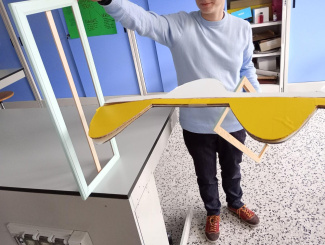
Fig. 6: This clearly shows how just the field oscillating in a specific plane can pass through
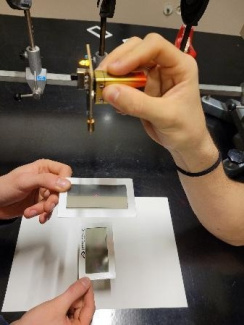
Fig. 7: A polarisation filter for laser light
Another way to polarise light is by using a particular kind of crystals, called birefringent. They split up unpolarised light passing through them into two rays whose polarisation directions are perpendicular to each other. This has an effect on what we see: the objects seen through the crystal appear twice.
See “Splitting and reuniting laser beams - with birefringent crystals”.
Using Iceland spar, also called optical calcite (CaCO3), students can investigate the phenomenon of birefringence by observing drawings they made on white sheets of paper. You can easily order Iceland spar, also known as Iceland crystals, online.
By putting a polarisation filter on the crystal, one can demonstrate that the polarisation directions of the two emerging rays are perpendicular to each other.
The students do the activities on the worksheet 'Birefringent Crystal and Light Polarisation'. Download it as PDF or docx.
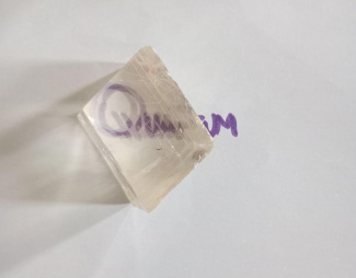
Fig. 8: Birefringent effect of a calcite crystal
A word (“Quantum” in figure 8) is written on a sheet of paper, and the calcite crystal is placed on top of it. When looking through the crystal, the word is visible twice due to the birefringent nature of the calcite – which sends polarised light into two different directions that are perpendicular to each other. Then, one places a polarisation filter between the word “Quantum” and the crystal (see fig. 9). The polarisation filter should be marked at one corner for its orientation to be identifiable. The filter is then rotated relatively to the crystal until one of the two words (i.e. one of the two polarised beams) becomes invisible. Students could take a picture of this orientation. They can also observe that this arrangement of a birefringent crystal and a polarisation filter may also be obtained using two polarisation filters (also called polariser and analyser) being placed perpendicularly to each other: the polariser polarises light in a specific direction which is then totally blocked by an analyser which is placed perpendicularly to the first polariser (no components of the electric field remain).
Secondly, the polarisation filter is rotated further, until the light beam which resulted in the word to become visible is now totally blocked, whereas the second light beam (that was blocked in the first step) now makes the word become visible. The students will notice that this second rotation of the crystal corresponds to a rotation of 90 degrees with respect to the end position of the first rotation.
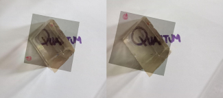
Fig. 9: A polarisation filter is placed onto a calcite crystal
Experiment 2: How light passes the polarisation filters
Material
- A big laser with supports, polarisation filters (for demonstration by the teacher)
- Small laser, polarisation filters for student groups
- The Phyphox app on the students’ tablets/smart phones (to measure light intensity)
Caution: When using lasers, you should take some precautions and tell your students that they must avoid pointing the laser beam directly towards their or their peers’ faces, or even worse towards their eyes, because powerful lasers can damage the eyesight. Please also follow any safety regulations applicable in your country or institution.
Switch on the laser and show the path of the light beam without any polarisation filter. Use a screen to “stop” the light beam – a light spot is visible when the light reaches the screen.
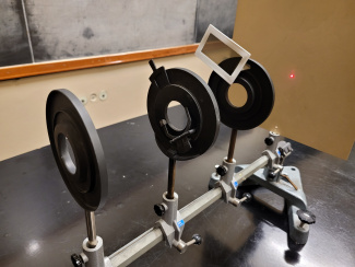
Fig. 10: Experimental setup: optical bench with mounts
Invite the students to observe the straight trajectory of the light beam. Insert the first polarisation filter in the light’s trajectory by fixing it on the first optical mount (see fig. 11).
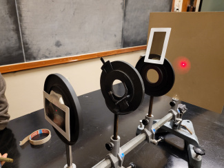
Fig. 11: Setup with optical mounts and polarisation filters
Ask the students if they observe any change in light intensity. The light intensity should have considerably decreased unless the polarisation filter happens to be aligned with the polarisation direction of the laser light. Tell the students that the polarisation filter polarises the laser light in one single direction, even though we do not know its exact polarisation direction (yet). For the teacher: usually, the polarisation direction corresponds to the short side of the filter frame (see fig. 12).
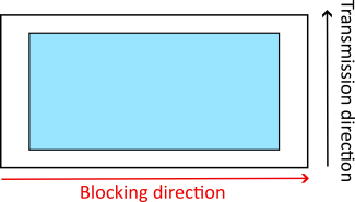
Fig. 12: Blocking and transmission direction of a polarisation filter: the locking direction is the one where light with a component of the electric field in this direction is absorbed by the polarisation filter, while the transmission direction is the one where light with a component of the electric field in this direction passes through the filter.
The light intensity, or, qualitatively, its brightness, has decreased because part of the laser light could not make it through the polarisation filter, it has been “absorbed” by the polarisation filter. Light that could get through the polarisation filter has a decreased intensity, which for an ideal polarisation filter is given by Malus’ law:
is the incoming light intensity, which is measured in \( \mathrm{W/m^2} \) , and is the angle between the polarisation direction of the polarisation filter and the polarisation direction of the incoming light beam. For any transition of a polarisation filter, “incoming light” means “the light beam before hitting the filter, whereas “light through” means the light that passes the polarisation filter and continues its path. The light that does not make it through is absorbed by the polarisation filter. The students can verify Malus’ law by measuring the light’s intensity – using an app on their smartphone (for example Phyphox) – as a function of the angle .
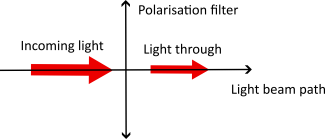
Fig. 13: Polarisation filter and light intensity
The students can verify Malus’ law by measuring the light’s intensity – using an app on their smartphone (for example Phyphox) – as a function of the angle .
Polarisation is a phenomenon that can be explained with the wave nature of light.
Now insert the second polarisation filter, so that its polarisation direction is perpendicular to the polarisation direction of the first polarisation filter.
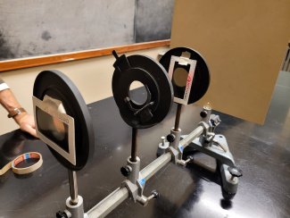
Fig. 14: Adding the second polarisation filter
Ask the students to describe what they observe. Their answer will be: no light can be seen on the screen. Ask them how they can explain their observation.
After a while, their explanation will probably be: only light with a nonzero component in the direction of the filter’s polarisation direction (e.g. the vertical component) passes the first polarisation filter, whereas the second polarisation allows only light polarised horizontally to pass. However, since the first polarisation filter absorbs horizontally polarised light, no light passes through the second filter. Well, this is consistent with our wave view of light.
At this point, the students can measure the light intensity passing the second polarisation filter with their smartphones – depending on the angle between the polarisation directions of the two polarisation filters (e.g. 0°, 30°, 45°, 90°). By doing this, they can check whether Malus’ law also works with several polarisation filters in a row. It should be noted, however, that Malus’ law is only exactly valid for ideal polarisation filters, so you should be happy with approximations.
Now, turn the two polarisation filters to their previous positions, so that their polarisation directions are perpendicular to each other. Insert a third polarisation filter between the other two with its polarisation direction tilted by 45° with respect to the horizontal direction.
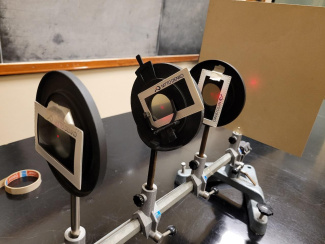
Fig. 15: Setup with three polarisation filters: the polarisation directions of the two at the ends are perpendicular to each other, the polarisation direction of the one in the middle is tilted by 45° with respect to the horizontal direction.
Ask the students what they expect to see on the screen. Before switching on the laser beam, let them think about it for some minutes, so that they can come up with their own ideas and “theories”. Give them the time to debate on possible outcomes and compare their theories.
Switch on the laser beam. The big surprise now is that some light passes through: a light spot can be observed on the screen.
Ask your students to try to explain theoretically what is happening. Allow some time so that they can reformulate what they said before. Would they have predicted this before having seen it?
The first polarisation filter polarises the light vertically, i.e. in a plane that is tilted by 90° with respect to a horizontal axis. Only light whose component oscillates vertically passes this filter. Subsequently, part of the light passes through the 45° polarisation filter (see fig. 16 to 18), and the third polarisation filter, which is tilted by 90° with respect to the first polarisation filter (0° with respect to the horizontal axis). Only the horizontal component of the light that was polarised in the 45° direction is now transmitted (see fig. 16).
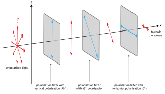
Fig. 16: Light path through the three polarisation filters.
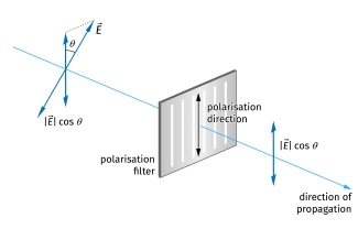
Fig. 17: How a polarisation filter works. Polarisation is a phenomenon that can be explained with the wave nature of light.
Short digression on vectors
Read more on "Short digression on vectors" below:
Fig. 18 depicts how to decompose the polarisation vector – which indicates the polarisation direction. For vertically polarised light the electric field oscillates vertically: the horizontal component of the electric field is and the horizontal component is , , . For horizontally polarised light, the horizontal component of the electric field is and the vertical component is , , . The length of the vectors is chosen to be , we are merely interested in the direction of the polarisation. Fig. 18 also shows the case of a light wave with 45° polarisation. Decomposing the corresponding polarisation vector results in the horizontal and vertical components having equal lengths: Since in wave optics the square of the vector’s length is proportional to the light intensity, a 45° polarisation filter, for example, allows i.e. half of the intensity of the vertically polarised light to pass through.
From now on, we designate the two vectors for vertical and horizontal polarisation as basis vectors, written as column vectors: und . The light wave with a polarisation of 45° may be described by the following vector: In general, the vector describing the polarisation direction of a light wave may be written as
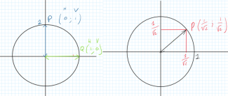
Fig. 18: Vector decomposition of the polarisation vector with vertical and horizontal components. Left: vertical and horizontal polarisation. Right: 45° polarisation.
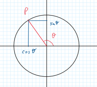
Fig. 19: Vector decomposition of the polarisation vector – general case
Polarisation in the particle picture
Up to now, we have described everything in the “wave picture” of the light, but what about the particle picture? In the particle picture, light consists of many extremely small quanta of energy, small particles, called photons. Any single one of these photons passes through the polarisation filter … or not. How can we explain the behaviour that we just observed in the particle picture? If we describe light as a beam composed of a large number of photons, the light intensity is proportional to the number of photons. In this case, students can use Malus' law with regards to , the number of photons emitted by the laser and , the number of photons that pass through the polarisation filter: But what would happen if only a single photon would hit the polarisation filter? Photons are indivisible, so we cannot say that only one part of a photon passes the filter. We need to use another mathematical approach to describe it. We need to work with probabilities. The probability for one photon to pass the polarisation filter is given by Malus' law which must be adapted for a small amount of photons. If each photon passing through the polarisation filter has a certain probability of passing through the filter, this can be written as follows: The light intensity measured after the polarisation filter is proportional to the incoming light intensity multiplied with the probability that a photon passes through the polarisation filter. For a large number of photons, one can again use the classical version of Malus’ law (right part of the equation above).
When the polarisation direction of the photon and the polarisation direction of the polarisation filter are parallel, , i.e. . When both polarisation directions are orthogonal, , i.e. . The square of ensures that we get a positive result between 0 and 1 – which is suitable to describe probabilities.
For the time being, we assume that polarisation is a property of the photon, a characteristic that we will not examine in detail at this point.
| Angle | cos | cos² | Intensity I |
|---|---|---|---|
| 0° |
|
|
|
| 30° |
|
|
|
| 45° |
|
|
|
| –45° |
|
|
|
| 90° |
|
|
|
Table 1: Relation between the polarisation direction of the polarisation filter and the light intensity behind the polarisation filter
The probability for a photon to be absorbed is:
Connection to quantum physics
Now let's slowly try to establish a connection to quantum physics. When a photon is polarised horizontally, it is in a specific “ state ” that we can write as . When a photon is polarised vertically, it is in the state , and it is in the state for any other polarisation direction. A special feature of the states and is that they are independent of each other: A vertically polarised photon cannot be “horizontally polarised” at the same time, and vice versa. This means that the two states “vertically polarised” and “horizontally polarised” are mutually exclusive.
Let us go back to the polarisation filters. They interact (“do something”) with the incident light. The light that is transmitted by the polarisation filter allows conclusions to be drawn about the polarisation of the incident light. This corresponds to a measurement : the polarisation filter examines the incident light, so to speak. A polarisation filter with a vertical polarisation direction allows the photon to pass through if it is vertically polarised and absorbs it if it is horizontally polarised.
Now, let us examine the experiment with the three polarisation filters again (see fig. 15 and 16). The middle polarisation filter with a polarisation direction of 45° analyses whether the incident photon has a non-zero polarisation component in the 45° direction. Actually, the photon that made it through the polarisation filter with horizontal polarisation direction does have a component in the 45° direction. And this 45° component has, in turn, a vertical component which passes through the third polarisation filter.
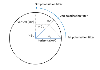
Fig. 20: The photon interacts with the various polarisation filters– first with the one with horizontal polarisation direction, then with the one with a polarisation direction of 45°, and lastly with the polarisation filter with a vertical polarisation direction. The probabilities that a photon can pass the filters is given by the length of the red arrowsblue lines.
In the particle approach, the probability that a horizontally polarised photon passes the 45° polarisation filter is . The probability that it subsequently passes through the polarisation filter with vertical polarisation is again . The overall probability that a single photon is able to get through these two polarisation filters is: . So, some photons will be able to reach the screen after having passed all three polarisation filters! We can’t tell whether a specific single photon will make it through, but statistically, one out of four photons will pass through the last two polarisation filters.
Remark about lab lasers
Normal lab lasers emit polarised light. This means that you can avoid using the first polarisation filter, two would be sufficient. You should know the polarisation direction of the light emitted by your laser. You can analyse it using a polarisation filter. Just find out the direction where the least laser light is transmitted (ideally none). The polarisation direction of the laser light corresponds to a direction that is perpendicular to that one.
O3Q.de – Low-Cost Experimente zur Wellen- und Quantenoptik
(last accessed 20.03.2026)Ghirardi, Gian Carlo. "Un’occhiata alle carte di Dio: Gli interrogativi che la scienza moderna pone all’uomo" Il Saggiatore, Milano, 1997.
Bondani, Maria. "Single‑photon Mach‑Zehnder interferometry for High Schools." Journal of Physics: Conference Series, vol. 1929, no. 1, 2021.
M.Michelini, G.Zuccarini. "Promoting the transition to quantum thinking: development of a secondary school course for addressing knowledge revision, organization, and epistemological challenges" Cornell University ARXIV, 2022.
Share this page